Fragen zum Thema BUS
How to connect a BACnet MS/TP network with a PC?
An existing BACnet MS/TP network has to be connected to a PC in order to configure the included devices.
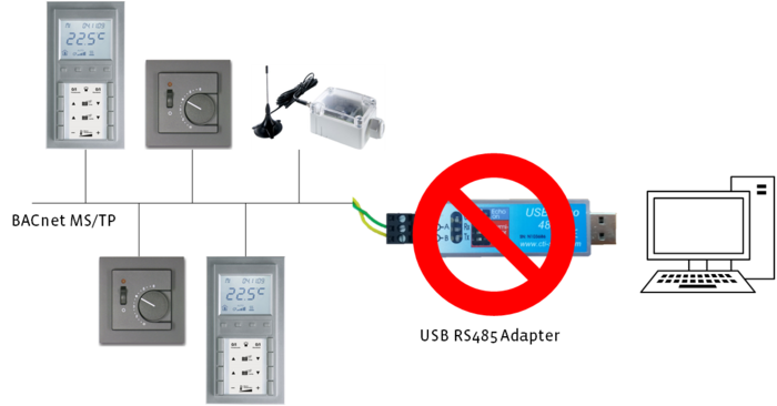
BACnet MS/TP technology interacts with strictly timely coordinated actions within the reach of 1ms. The BACnet MS/TP networks are based on the serial interaface standard RS485. The communication between these RS485 MS/TP network and the serial interface of a PC can cause undetermined time delays. Therefore a reliable communication can't be guaranteed. This issue occurs with windows operating systems especially and is caused by the technical implematation of the serial interface within the operating system itself. Therefore it can't be affected.
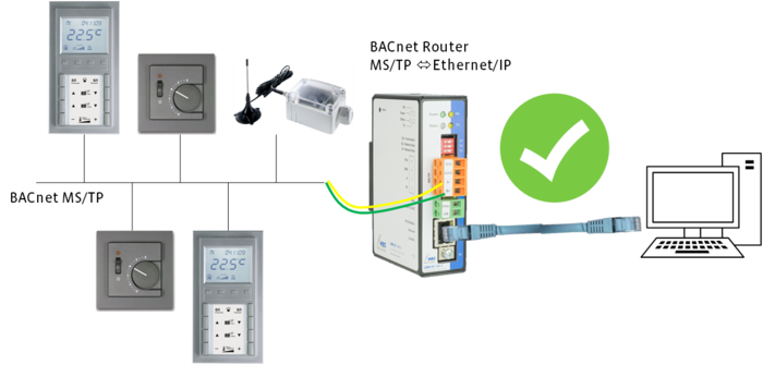
The configuration of BACnet MS/TP networks can be done with routers also. These routers connect the MS/TP network with the Ethernet/IP interface of the PC. So possible timming problems of the serial interface are avoided.
Now, a connection to the BACnet MS/TP network can be established by a suitable software like BACeye or others. Oftentimes these Ethernet/IP ⇔ MS/TP router are part of a BACnet controller. They are also available seperately (e.g. MBS UBR-01 | Mk II BACnet).
Note:
Some software tools offer the possibilty to connect the RS485 BACnet MS/TP with the PC directly by the serial interface. Nevertheless Thermokon recommends the solution with MS/TP ⇔ Ethernet/IP. This solution works more reilable and can guarantee a proper communication with the BACnet devices.
Why does my Modbus device not work reliably?
In case of an occasionally working Modbus device, there is probably an interference on the RS-485 interface. This interference might cause a function failure of the device. But it doesn’t constitute a defect of the same.
To avoid these interferences you have to note some important remarks when wiring RS-485.
1. Type of line
Generally we recommend to use a twisted and shielded 2-wire cable. For example: J-Y (ST) Y or BELDEN 9841.
2. Line connection
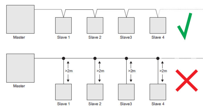
Connect your devices in a row. Try to avoid tab lines. The distance to each Modbus device should not exceed 2 m.
3. Termination resistor
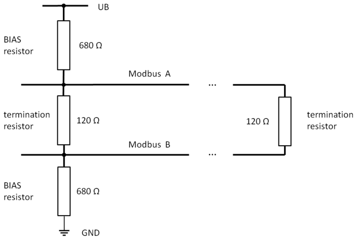
To avoid reflections on the BUS line, the RS-485 has to be stabilized with 2 termination resistors. One at each end of the line.
The RS-485 specification recommends the connection of 120 Ohm resistors between the two BUS lines. (as shown below). Most Thermokon devices offer the possibility to activate theses resistors. For further Information please have a look at the corresponding data sheets
4. BIAS resistor
BIAS resistors are used to stabilize the BUS line to a defined voltage level, when there is no communication on the BUS. So invalid signal states are avoided.
They have to be installed at just one position of the BUS line. Usually Modbus masters (DDC, PLC, etc.) offer the possibility to activate these BIAS resistors. Field devices are usually not equipped with BIAS resistors. In case your controller (Modbus master) does not provide integrated BIAS resistors, Thermokon provides the option to integrate these in one of your Modbus field devices. Please see our offered additional BIAS-board to connect with the field device. - Article number: 618823
What is the baud rate and parity?
What is the baud rate?
The Baud rate describes the amount of transmitted symbols per unit of time. To ensure a proper Modbus communication, every device in a line must send with the same Baud rate.
A higher baud rate provides a higher data transmission, but is also more vulnerable for interferences.
What is the parity?
This mechanism is used to detect bit errors during transmission. Therefore every message at the BUS contains a so called “parity bit”.
To calculate the parity bit, the horizontal checksum of the data bits is generated. The checksum together with the parity bit must yield an odd or even number. It depends on the specific settings for this BUS line. This setting has to be equal for every device in the line in order to ensure a BUS communication.
How many Modbus participants are possible?
The maximum amount of Modbus participants in a row is determined by the used Modbus transceiver in the devices.
If there are different devices used in a line, the smallest number of accepted devices becomes effective. Thermokon devices support maximum 32 Modbus participants. More than 32 Modbus participants are possible exlusivley with an external RS-485 Modbus repeater. An exception is the Thanos. These device supports maximum 128 participants.
For time critical applications like the dim of illumination or the adjustment of blind slats the number of participants should be as small as possible. Otherwise the Modbus characteristics could cause a noticeable time delay.
The Thermokon USEapp provides the possibility to assign addresses from 32 to 247. However, this has no effect on the maximum amount of participants. This function is only provided for a clear structure.
Why can't I establish a connection to my Modbus device(s)?
Every Modbus system works as a Master-Slave. The master (DDC, PLC, etc.) organizes the communication and the slaves (sensors, valves etc.) listen to the master. Thermokon devices are exclusively slaves.
In order to ensure a proper communication between the master and the slaves, following settings have to be obtained:
1. The baud rate of the master and the slaves has to be the same on the whole line.
2. The set parity also has to correspond between the line participants.
3. Every slave needs a specific and unique address. Duplications are not allowed. The adjustment of the address can be done in the devices directly. Further information regarding the adresses of Modbus devices can be found in the corresponding data sheets.
4. The BUS lines A and B must not be interchanged! Consider the corresponding markings on the devices when connecting.
5. If several devices are connected with AC power supply the connection lines must not be intercharged among each other.
How to connect a Modbus device to a computer?
A USB-RS485 adapter provides the possibility to take hold of RS485 interfaces with a computer.
For that, we recommend the CTI USB-Nano-485. This adapter is also used for internal development and support – Article number: 668293
Prior to a first usage, the installation of the corresponding FTDI driver is necessary. Usually, the driver is downloaded and installed automatically. You also got the option to download and install manually, in case the driver can’t be found and installed:
http://www.ftdichip.com/Drivers/VCP.htm
Optionally, you’ll find the drivers on the CD delivered with the USB adapter. In addition ensure that you have admission rights to install the serial interface driver to your computer.
What means the message 'Illegal Data Value'?
The message "Illegal Data Value" is a Modbus exception reponse. This error message occurs if too many modbus registers are to be read out at once. This causes an invalid Modbus request.
The number of register must be between 1 and 125 due to Modbus specification. Possible exepticons are pecified at corresponding product documentation.
Note:
The valid register quantity is supervised by many Modbus masters automatically. Oftentimes the message "Illegal Data Value" is the result of undefined voltage levels on the buslines. These can be interpreted as invalid modbus requests. In order to avoid these undefined voltage levels, provide the Modbus line with BIAS resistors.


