Fragen zum Thema EasySens®
Which devices can be configured with airConfig?
The following devices are compatible with airConfig and can be configured via the software:
What is defined as a "good" signal strength?
The signal strength of EasySens® radio sensors is indicated with an RSSI value. RSSI means Received Signal Strength Indicator. This value is essential as it indicates the signal strength.
The RSSI value is shown in airScan or other tools when an EnOcean telegramm has been received. The higher the RSSI, is the better the singal strength is.
ATTENTION: The RSSI value is displayed negative!
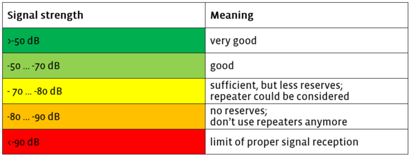
The values have the following meanings:
Note:
The RSSI values shown in airScan refer to an internal antenna on the EnOcean USB Transceiver. If the receiver uses an external antenna, the real RSSI value is about 5 dB higher.
Do not connect the USB Tranceiver directly to an USB port of your PC because the near surroundings could have an influence on the measurement values. Use an USB extension or USB hub instead.
Try to improve the signal strength at your receiver with a good radio planning instead of using repeaters unnecessarily!
What is the threshold hysteresis?
The threshold hysteresis describes the value change that must occur so that an EasySens® sensor sends a new data telegram.
This hysteresis ensure that a new data telegram is just send if the measurement value has changed about the hyteresis value since the last measurement. This procedure is neccessary so that EasySens® sensors can work energy self-sufficient.
Example 1:
| Measuring range: | 0 °C bis +40 °C |
| Hysteresis: | ±0,8 °C |
| Last temperature value: | +21,5 °C |
The sensor will transmit a new data telegram, if the temperature is lower than 22,3 °C (21,5 °C + 0,8 °C) or higher than 20,7 °C (21,5 °C - 0,8 °C) with the next measurement.
Example 2:
| Measuring range: | -20 °C bis +60 °C |
| Hysteresis: | ±0,64 °C |
| Last temperature value: | +18,3 °C |
The sensor will transmit a new data telegram, if the temperature is lower than 18,94 °C ( 18,3 °C + 0,64 °C) or higher than 17,66 °C (18,3 °C - 0,64 °C) with the next measurement.
The hysteresis value dependes on the measurement range thus from the used EnOcean Profil (EEP).
Exclusively the SR06 LCD provides the possibility to change the hysteresis value with airConfig or the SR06 LCD configuration software.
How often does an EnOcean radio sensor transmit a telegram?
For reasons of energy saving, the EnOcean radio sensors transmit their values at preset intervals. Usually these intervals can be parameterized.
They consist of two components:
1. The WakeUp Time
This parameter describes the time period the sensor wakes up and performs a measurement. Though the result of this measurement is only transmitted if the <link record:tx_ricodynamicfaq_domain_model_question:tx_ricodynamicfaq_domain_model_question:65 _self>hysteresis value</link> is exceeded. If this value is not exceeding the hysteresis value, the sensor sleeps until the next measurement is performed.
2. The Heartbeat Cycle
This parameter describes the amount of measurements after which a new telegram is sent, even if the measured value has not changed signficiantly since the last measurement. This gives an indication to the receiver that the transmitter is still in operation - comparable to a heartbeat.
WakeUp Time and Heartbeat Cycle can be adjusted at most devices. This is done by integrated plug-in jumpers or software tools e.g. airConfig. Further Information on these parameters can be found in the corresponding datasheets.
Example:
| WakeUp time: | 100 s |
| Heartbeat cycle: | 10 |
| Send interval at very small value change: | 100 s x 10 = 1000 s ≙ 16,67 min |
Note:
WakeUp time and heartbeat cycle have a direct influence on the energy consumption of the device. A very short interval can drag the energy storage faster than it is charged. In addition the danger of a telegram collision and data loss increases with higher transmission intervals.
Why doesn't the display of the SR06 LCD stay active all the time?
The display of the SR06 LCD can be parameterized as follows:
1. ON at button push (with off-delay time)
2. Always on
The second function is only recommended to be chosen, in case the additional battery is inserted and the solar cell can gain sufficient energy daily.
If the display switches off having „Always on“ activated, one of the conditions is not fulfilled.
Insert the additional battery CR1632 (article number 597814) and/or place the device in a location, where there is sufficient illumination over the day.
Note:
The permanently activated display might lead to an exhaustion of the energy storage despite the inserted additional battery. This function is only recommended for evaluation and commissioning purposes.
Further information can be found in the Datenblatt.
How and where to use a repeater?
The use of repeaters requires a careful and detailed planning. On one hand, repeaters try to solve radio range problems. On the other hand, they can cause a significantly higher radio occurrence not always improving the situation.
Repeaters may only be used, where the signal you want to repeat still has a sufficient signal strength . That means: RSSI>-80 dB
Repeaters are ought to be placed centered between transmitter and receiver with similar distances to each side.
It is necessary to find out, which radio signals have to be repeated. Try to avoid repeating ALL radio telegrams that reach the repeater. This complicates the commissioning and causes a higher radio occurrence. Please note the information on repeater parameterization.
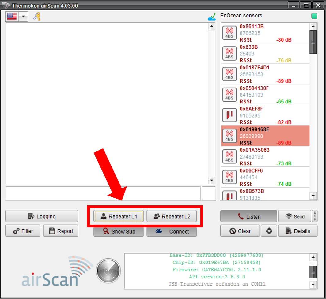
The right position for a repeater can be determined by the software tool airScan. If the radio range of an application is not sufficient place the EnOcean USB Transceiver nearly centrally between the transmitter and the receiver. Activate now the needed repeater level 1 or level 2.
Ensure that the radiotelegrams receive at the revceiver properly. After that test install a independent repeater SRE-Repeater or SRE-Repeater UP at the location in order to ensure a reliable radio communication.
Note:
The integrated repeater function of airScan is just for commisioning or troubleshooting issues because of the EnOcean USB Transceiver's limited antenna range.
Which radio range can EnOcean devices cover?
The data sheets of Themokon EnOcean products advise the maximum radio range to be around 30 m (100ft) in buildings. Outdoor applications can cover longer distances.
This is exclusively valid for ideal conditions which are very rare in reality:
- No shielding of the transmitter
- Unobstructed transmission path
- No shielding of the receiver
To ensure a proper radio connection, please obtain following guidelines:
1. Ensure that the transmitter transmits without interferences. Use airScan to measure the radio telegram’s signal strength (RSSI) of a transmitter close to the intended receiver installation spot.
2. Ensure that the radio telegram is received at the receiver with sufficient reserves. Measure the radio telegram’s signal strength with airScan close to the antenna of the receiver. If no antenna is used, measure the signal strenght right at the receiver.
3. Perhaps the radio telegram reaches at the receiver, but causes no reaction or with very low signal strenght. In that case, the transmitter may send telegrams, but is possibly not correctly learned into the receiver or causes information losses during normal data transmissions.
If the radio telegram does not reach the receiver with a sufficient signal strenght, try to bring one of both (receiver or transmitter) closer to each other or in a better position. That means less distance or less shielding. In case that this won’t lead to significant improvements, the use of wireless repeaters is possible.
If an existing radio communication is disturbed, one of the following reasons might cause the disturbances:
1.Interrupted/Obstructed transmission path
An interruption of the radio communication might be caused due to additional furnishings or similar. Ensure that there hasn’t been a change on the radio path that might have caused this interruption i.e. objects like furniture do not block or dampen the signal strength.
2. Exhausted energy storage of the transmitter
Most Thermokon EasySens® transmitters are designed for an energy self-sufficient operation. The data sheets of these devices declare the conditions that must be fullfilled such as minimum light levels during the day.
If these conditions are not met, the energy use can exceed the energy generation and lead to exhausted capacitors. If no measures are taken, the device will run out of energy and stop any radio transmission.
Singal strength measurement
Thermokon provides the airScan tool for signal strength measurements and improvements on the radio range.
Why gets the type of my device or sensor not shown in airScan?
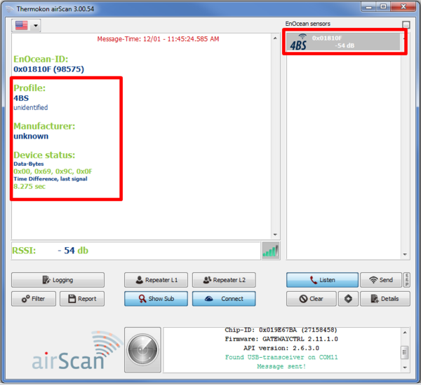
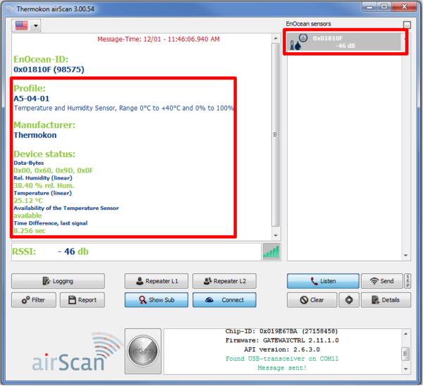
The frequently sent EnOcean telegrams are shown in airScan. The sensor type and the EEP profile are not part of these data telegrams. These are only transmitted when the learn telegram is sent.
This learn telegram is sent by pressing the learn button on the device. If the learn telegram is sent, the sensor type and EEP profile are shown in airScan. Now transmitted data are decoded and shown.
Why does my controller not control based on the adjusted set point?
EnOcean room operating units transmit the set point shift not as an absolute value (temperature or humidity).
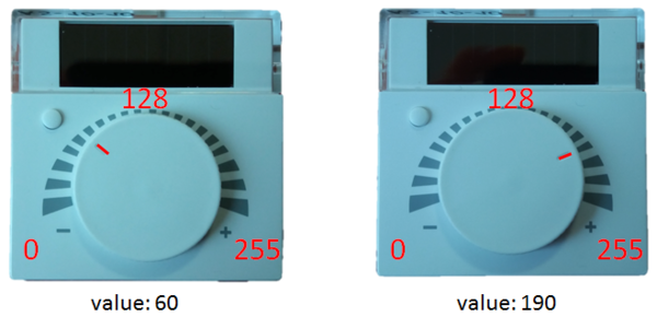
It is transmitted as a relative shift from 0 to 255 (1-byte value). This value shows e.g. the angular position of the rotary potentiometer:
The transmitted value is added/deducted to/from the base set point of the receiver. For some products it is necessary, that both the transmitter and receiver have the same identical base set point!
Example below for a possible set point offset of ±4 °C
| Transmitted number value ROU | Set point offset |
| 0 | -4 °C |
| 50 | -2,4 °C |
| 90 | -1,2 °C |
| 128 | ±0 °C |
| 160 | +1,0 °C |
| 205 | +2,4 °C |
| 255 | +4 °C |
The control variable depends on the adjusted base set point and the possible set point offset of the receiver.
Base set point ± set point offset
Application expample:
SR07:
| Transmitted set point offset ROU: | 240 bit (transmitted value SR07) |
STC-DO:
| Base set point: | 21 °C |
| Possible set point offset: | ±4 °C |
| Effective set point offset: | 240 bit; are interpreted as +3,5 °C |
| Control variable STC-DO: | 24,5 °C |
How the hysteresis-value is determined?
The hysteresis-value with EnOcean Sensors is determined in LSB. The abbreviation stands for least significant bit.
With the EnOcean profils (EEPs) temperature, humidity and other values are transmitted as 1-byte value. That corresponds to a scale of 0 to 255 (1-byte).
The EEP‘s range of values is now mapped on this number range. A measurement range from 0 °C to +40 °C now corresponds to the number range of 0-255.
Thereby the LSB describes the smallest possible change within this range, namely 1 bit.
Example:
EEP A5-02-05 temperature 0 °C to +40 °C
Resolution temperature:
40 °C / 256 = 0,16 °C/bit
5 LSB = 0,16 °C/bit x 5 bit = 0,8 °C
2 LSB = 0,16 °C/bit x 2 bit = 0,32 °C
EEP A5-04-02 temperature -20°C to +60°C | humidity 0 bis 100%
Resolution temperature:
80 °C : 250 = 0,32 °C/bit
5 LSB = 0,32 °C/bit x 5 bit = 1,6 °C
2 LSB = 0,32 °C/bit x 2 bit = 0,64 °C
Resolution humidity:
100% : 250 = 0,4%/bit
5 LSB = 0,4%/bit x 5 bit = 2%
2 LSB = 0,4%/bit x 2 bit= 0,8%
So the hysteresis value of the various EnOcean sensors depends on the used EEP and the LSB sensitivity of the device (2 LSB or 5 LSB).
How can I use both of the SR06 LCD's lower buttons for light or blind control?
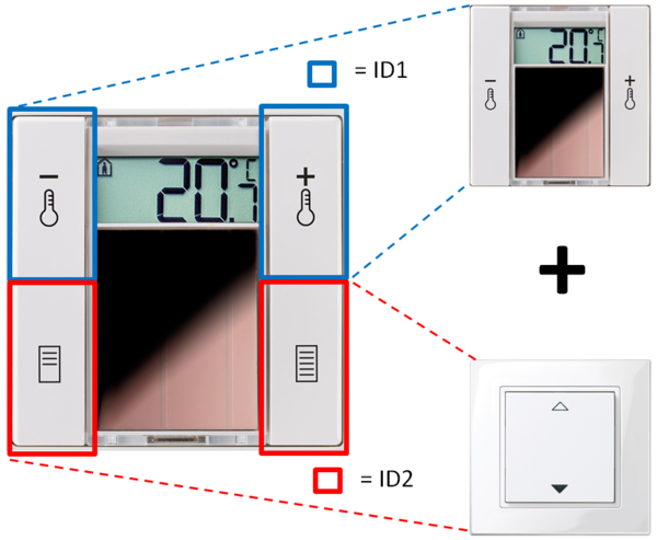
The SR06 LCD 2T Light and 2T Blind combines two devices in one. One SR06 LCD 2T wireless thermostat and one rocker switch. Therefore the device has 2 EnOcean Send-ID’s.
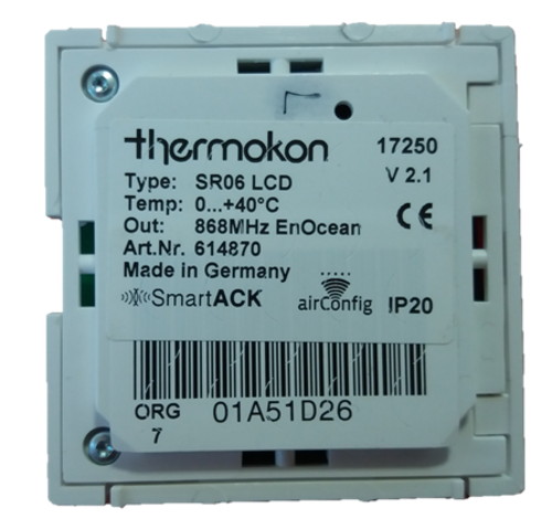
The upper buttons have the same functionality as the SR06 LCD 2T – changing setpoint temperature. The EEP profile A5-10-03 is chosen as default configuration and used for temperature control. For this, the Send-ID 1 is used. It is printed on the label on the backside of the device.
The lower buttons work as a 2-channel rocker switch with EEP profile F6-02-01. They can either be used for light or blind control.
The second Send-ID can be identified by pressing on one of the lower buttons and checking the incoming EnOcean rocker switch telegram with airScan.
Why does the SR06 LCD display remain switched off after a key press?
The SR06 LCD is delivered in the so called “shipping mode”. In this mode, the whole radio communication is turned off. No telegrams are sent and the display is turned off as well.
The reason behind is to preserve the energy storage during transport and storage.
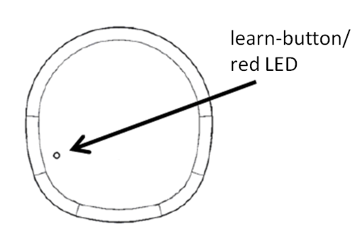
With a long key press (> 2 seconds) on the learn button on the back side, the SR06 LCD can be put into the operation mode.
The SR06 LCD configuration software makes it possible to put the device back into the shipping mode e.g. for transport or storage.
Why the SAB05/SAB+ can't be mounted on a valve?
For mounting an SAB acutator on a valve, the drive spindle of the actuator has to be retracted completely.
If this is not the case, please proceed as follows:
SAB05
Open the case cover, remove the batteries wait 10 seconds and reinsert them.
The SAB05 drives into mouting position (drive spindle completely retracted) and can now be mounted on a valve. When successful, it is ready for normal operation again.
SAB+
Press the learn button on the back of the device for about 5 seconds.
The SAB+ drives into mounting position. The drive spindle is retracted completely and the radio communication is switched off.
After the SAB+ has been mounted on the valve, press the learn button again for about 1 second. Now the SAB+ is ready for normal operation again.
How to prevent theft and vandalism of SAB actuators?
Unfortunately, the theft of or vandalism at SAB actuators occurs. To avoid this, the following measures can be taken:
SAB05
Battery protection: The battery protection SAB05 (item no. 595612) prevents theft of batteries.
The battery compartment can be locked by a special screw requiring a tool.
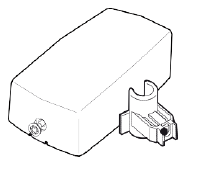
SAB05 and SAB+
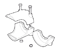
The saftey lock dismounting protection SAB (item no. 706148) prevents the tooless disassembley of an SAB actuator from a valve.
This protection covers the securing nut of the SAB actuator.
How can I access a devices in airConfig?
Before you can parameterize a device with airConfig, it must be displayed in the airConfig software. There are two different ways, depending on the type of device:
1. Devices with permanent power supply:
By right-clicking on your device at the driver list choose „Query devices“. After a short search your device appears in the devices list and can be accessed for parameterization.
2. Devices with interrnal energy storage:
These devices have a learn button. If airConfig is running with an EnOcean USB Tranceiver and the learn button (LRN) is pressed, the device appears in the device list. Now it can be parameterized and the configuration can be sent back once finished by right-clicking and pressing „Send configuration“.
Note:
The room operating panel SR06 LCD appeares after a long press (about 2 seconds) on the learn button
Why doesn't airScan/airConfig recongnize the EnOcean USB transceiver?
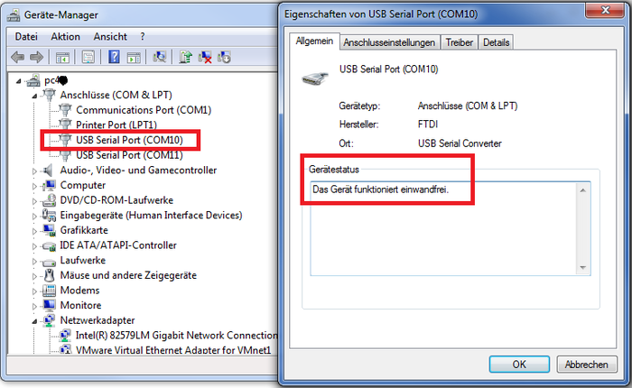
Thermokon provides an EnOcean USB transceiver for the software tools airScan and airConfig. Before using the USB transceiver for the first time, the driver needs to be installed correctly.
If it is not installed on the computer, it will be automatically downloaded from the Windows website. If this is not the case, you also got the option to download and install the driver manually using the following link:
http://www.ftdichip.com/Drivers/VCP.htm
Now, the USB transceiver is recognized by airConfig and airScan and can be selected:
If this is not the case, check the device management of your computer and ensure that the USB transceiver is set up properly as a serial interface. Also verify, that you have full access to the serial interface e.g. administration rights on your PC.
It is possible that the USB transceiver is displayed at the device management but not recognized by airScan or airConfig. This problem might be due to an outdated version of the driver. If it has been installed with an outdated driver for your operating system, make sure to install the latest version of the proper USB driver.
Note:
It is only possible to use the EnOcean USB-transceiver for one application at the same time. If airScan and airConfig should be used at the same time, two EnOcean USB Transceivers are required.
Why can't the airScan licence be activated?
The licensing process of our field-strength measuring tool "airScan" with the EnOcean USB stick has been changed. From now on, the licence is stored directly on the USB stick and is therefore independent of the end device (i.e. PC) used. This eliminates the need to reload the licence when changing computers. In addition, neither administrator rights nor network access will be required for licensing.
After updating to airScan version (V5.00) or newer, existing installations can simply adopt/write the registered licence onto the airScan stick. The licence previously stored on the computer loses its validity. You can then use the airScan stick independently of the PC.
With the new airScan version you also get access to the SensorCloud. All EEPs of the sensors that have been received with airScan in the past are stored in the cloud. This brings the great comfort of having sensor names always present inside a building, no matter who is checking the transmission ranges. If you have defined your own sensor names or positioning information in airConfig, these are transmitted to the SensorCloud. This means that the stored information are available on every computer using the airScan stick and moving inside the building.
For users having prejudices due to data privacy, the SensorCloud can of course be individually deactivated at any time.
Note:
The SensorCloud is hosted on an AWS server (Amazon Web Services)


